Q. How can moisture problems with pneumatically conveyed product be prevented?
A common problem with pneumatically conveyed products is condensation in storage after a pressure conveying system, which can lead to caking, clumping, mold, and mildew. To prevent the problem, we must first understand how the water got there in the first place.
Like pretty much everything else on this planet, most pneumatically conveyed products have some moisture content. Some have more, others less; for example, flour is 14% water and brown sugar is 1.8% water. The moisture content is liquid phase water, so heat will cause it to evaporate.
Pressure conveying systems heat the conveyed product. Although the discharge of a flour conveying blower is much too hot to touch, the line is comfortably cool just a few feet downstream of the airlock that feeds in the flour. This tells us that when the air and flour come together, the air cools and the flour heats. See our equilibrium temperature calculator for more detail.
Heating a moist product causes evaporation. Evaporation is inevitable because the higher temperature corresponds to higher water vapor pressure. For the same reason a cup of water cannot be heated to 101 C without flashing to steam, a moist product cannot be heated and still maintain the same level of moisture. There is nothing magic about 100 C; any increase in temperature corresponds to a higher vapor pressure.
Water Vapor Pressure
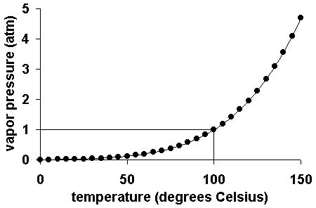
Moisture will evaporate until the conveyed product cools off. Evaporation doesn’t happen immediately, it takes time. Just like a clothes dryer, heat is added and evaporation (drying) takes longer.
When product is heated in a pneumatic conveying system, the amount of water vaporized is in proportion to the heat gain, not the moisture content of the product. That is why the same type of condensation that affects flour also affects sugar, even though sugar has much less moisture content.
Water vapor condenses to liquid when cooled. If heated product is pneumatically conveyed into a container, the cooling typically comes from the ambient air outside of the container. When water evaporates from the heated product, the vapor migrates to the sides and top where it cools and condenses, causing caking, clumping, mold, and mildew.
The solution to this problem is simple. Prevent the conveyed product from being heated in the conveying line. An air cooled heat exchanger is typically sufficient as it will cool the conveying air close to ambient temperature, preventing a subsequent cycle of evaporation and condensation.
Q. What is “Approach Temperature”?
This term refers to the temperature difference between the leaving process fluid and the entering service fluid. If air is cooled from 300 F to 100 F using 90 F cooling water, the air temperature approaches the water by 10 F (100 – 90 = 10). Such a heat exchanger is said to have a “10 F approach temperature.” The term “approach temperature” is used because it will stay fairly constant with changes in both inlet process and service fluid temperature.
As the approach temperature diminishes, the size (and cost) of the heat exchanger will eventually increase exponentially. One should be careful not to specify heat exchangers with unnecessarily small approach temperatures, as it can lead to costly over-design. Reasonable approach temperatures are usually:
- 15 F for water cooled heat exchangers
- 20 F for steam heated heat exchangers
- 25 F for air cooled heat exchangers
If you do not absolutely need a particular outlet temperature from your heat exchanger, let your designer know; they can use this information to offer you less costly alternatives!
Q. What is Dew Point?
The dew point is the temperature to which a given parcel of air must be cooled, at constant pressure, for water vapor to start to condense into liquid. The condensed water is called dew. The dew point is a saturation point. The dew point is associated with relative humidity; high relative humidity indicates that the dew point is close to the temperature. Relative humidity of 100% indicates the dew point is equal to the temperature and the water vapor (humidity) is saturated. When the dew point remains constant and temperature increases, relative humidity will decrease. At a given pressure, independent of temperature, the dew point indicates the mole fraction of water vapor in the air, and therefore determines the specific humidity of the air.
The below graph of a typical 24 hour period with roughly the same absolute humidity (dew point) illustrates the inverse relationship between temperature and relative humidity.
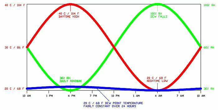
Find data for your area on Climate Charts world-wide map. Click on a nearby station to view a chart of daily high and low temperatures. The overnight low is often a few degrees below the daytime dew point.
Extreme Values
A dew point of 33 °C (91 °F) was observed at 2:00 p.m. on July 12, 1987, in Melbourne, Florida. A dew point of 32 °C (90 °F) has been observed in the United States on at least two occasions: Appleton, Wisconsin, at 5:00 p.m. on July 13, 1995, and New Orleans Naval Air Station at 5:00 p.m. on July 30, 1987. A dew point of 35 °C (95 °F) was observed at Dhahran, Saudi Arabia, at 3:00 p.m. on July 8, 2003. Dew points this high are extremely rare occurrences. Dew points higher than 80°F are rare, even in the tropics. The most humid USA design condition published by ASHRAE (American Society of Heating, Refrigeration & Air Conditioning Engineers) is Galveston, Tx: a 75.2 °F dew point, which is exceeded only 1% of the average summer, or about 30 hours.
The heat index below gives some perspective on dew points. Beware of a specification of “100 F, 100% RH” …as you can see it’s off the chart; it simply does not happen.
NOAA’s National Weather Service Heat Index
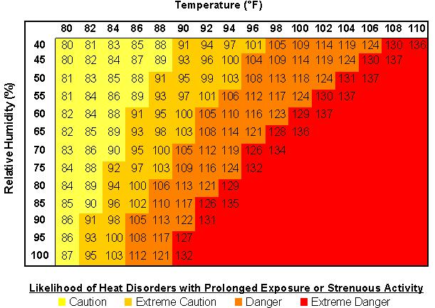
Humidity specified in terms of dew point is much simpler and less error-prone than the often misused term relative humidity. Relative humidity is often specified without an accurate reference temperature (to which the humidity is relative). For instance, it’s common to see something like: “Average temperature 55 to 94°F and relative humidity of 35% to 100%” for a location …but no mention of the fact that the 94°F occurs at 3 PM and the 100% relative humidity occurs at 3 AM when the air temperature is 65°F. Given the exponential shape of the dew point curve, it would grossly overstate the amount of moisture in the air to take data like this and presume the average high temperature/humidity is 94°F and 100% relative humidity.
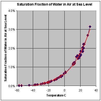
The capital and operating costs (e.g. refrigeration) of heat exchangers that cool below dew point are exponentially related to the specified dew point. Notice how the curve above is trending towards a vertical line as temperature increases. Overly conservative humidity specifications make projects financially unjustifiable and have kept a lot of beneficial systems on the drawing board. Please take care to specify a realistic dew point, or ask us and we’ll look up the ASHRAE design climate data for the installation site.
Q. How is heat transfer duty calculated?
Heat transfer can be classified in two ways:
Sensible heat transfer, also known as temperature change. For example, it takes one BTU to raise one pound of water one °F. The key relationship here is:
Q = Cp • M • TD
Where:
Q is BTU/hr
Cp is heat capacity in BTU/lb-F (the Cp of water is 1)
M is mass flow in lb/hr
TD is Temperature difference in °F
Latent heat transfer, also known as phase change. For example, it takes 1000 BTUs to boil one pound of liquid water into steam – at the same temperature. The key relationship here is:
Q = Hfg • M
Where:
Q is BTU/hr
Hfg is the latent heat of vaporization in BTU/lb (the Hfg of water is 1000)
M is mass flow in lb/hr
Q. How is heat exchanger performance calculated?
Heat exchanger design starts looking just as simple, but it gets much more interesting! Heat exchangers are machines that get fluids to transfer their heat. Most heat exchangers work with two fluids flowing through separate passages, for example cold water flowing inside a tube and warm air flowing outside the tube. When this happens, the cold fluid warms up and the hot fluid cools off. The key relationship here is:

Where:
A is the required amount of surface area in ft2
Q is duty in BTU/hr
U is the performance of the heat exchanger in BTU/hr-ft2-°F
LMTD is the mean temperature difference throughout the heat exchanger in deg F
Q. How is mean temperature difference calculated?
The LMTD is a computation that takes the inlet and outlet temperatures of both fluids and reduces them to one number, which is the average temperature difference:
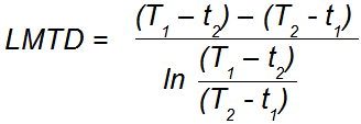
T1 = Hot Stream Inlet Temp.
T2 = Hot Stream Outlet Temp.
t1 = Cold Stream Inlet Temp.
t2 = Cold Stream Outlet Temp.
Q. How is a U value calculated?
The U value is the heat exchanger’s performance coefficient, it’s based on the unit’s design, materials and the fluids that flow through. A heat exchanger made from aluminum will have a higher U value than one made of plastic, because aluminum is a better conductor of heat. A heat exchanger using water as coolant will have a higher U value than it would using air as coolant, because water is a better coolant. The key relationship here is:

Where:
U is the performance coefficient for the heat exchanger in BTU/hr-ft2-°F
h1, h2, h3, etc. for a fin tube, air-to-water heat exchanger are heat transfer coefficients typically:
air, fin, tube, water.
R1, R2, R3, etc. is the thermal resistance of the various aspects of the heat exchanger in hr-ft2-°F/BTU, typically:
Internal fouling factor, metal contact resistance, external fouling factor
The number and type of heat transfer coefficients and thermal resistances will vary from one heat exchanger design to the next. In a simple unit where two fluids flow on opposite sides of a metal plate, there might be an hcold-fluid, Rmetal-plate and hhot-fluid. The metal resistance is trivial because the thermal conductivity of metals is well known. The fluid heat transfer coefficients depend not only on the fluid, but on it’s level of turbulence as it flows through the heat exchanger. Determining fluid heat transfer coefficients is often the crux of designing heat exchangers.
